In this blog, we will practically test MODBUS communication on an APFC 148 Controller.
This guide is based completely on a real practical demo, where we only verify whether communication is working or not.
This blog is helpful for electrical engineers, panel designers, automation learners, and technicians who want to test MODBUS communication quickly and correctly.
Why MODBUS Communication Is Important in APFC Panels
APFC controllers are often connected to:
- SCADA systems
- Energy monitoring systems
- PLC or HMI panels
- Data logging software
MODBUS communication helps in:
- Remote monitoring of power factor
- Reading capacitor step status
- Detecting alarms and faults
- Centralized energy analysis
Before integrating an APFC controller with any system, communication testing is mandatory.
What We Will Do in This Practical
In this practical session, we will:
- Test MODBUS communication on APFC 148 Controller
- Read Coil Status, Input Registers, and Holding Registers
- Use only default MODBUS settings
- Not change or validate any parameters
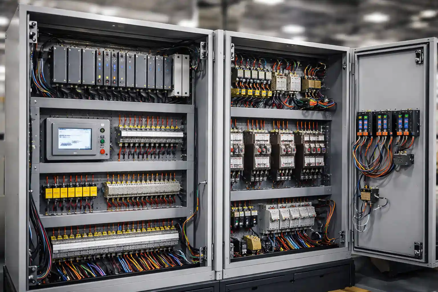
Hardware & Software Required
To perform this test, the following items are required:
Hardware
- APFC 148 Controller
- USB to RS485 Converter
- Laptop or PC
- RS485 communication cable
Software
- MODSCAN Software
- APFC 148 Controller Manual
Step 1: Connect the Controller to the Laptop
- Connect the USB to RS485 converter to the APFC 148 Controller
- Plug the USB cable into the laptop
- Power ON the controller
Step 2: Check the COM Port in Device Manager
On your laptop:
- Open Device Manager
- Go to Ports (COM & LPT)
- Check which COM port is assigned to the USB converter
This COM port will be used in MODSCAN software.
Step 3: Use Default MODBUS Settings
For this test, we will use default MODBUS settings of the controller:
- Slave ID – Default
- Baud Rate – Default
- Parity – Default
- Data Bits – Default
No settings are changed during this test.
Step 4: Open MODSCAN Software
- Open MODSCAN software
- Select the correct COM port
- Enter the default MODBUS settings
- Click on Connect
If all settings are correct, communication will start.
Step 5: Refer to MODBUS Register List
Before reading data, it is important to understand register types:
- Coil Registers – ON/OFF status
- Input Registers – Read-only measured values
- Holding Registers – Configuration and operational data
The exact register address and length are provided in the controller manual.
Step 6: Check Coil Status
First, we will check Coil Status:
- Start Address: 0
- Length: 13
Enter the address and length in MODSCAN.
You will see that communication starts immediately.
Step 7: Check Input Registers
Next, we will check Input Registers:
- Input Register Value: 83
- Register Length Used: 80
Enter the register length and test communication.
If values are visible, communication confirm ho jata hai.
Step 8: Check Holding Registers
Finally, we will check Holding Registers:
- As per manual, Holding Register Length: 60
Enter length 60 in MODSCAN and read the registers.
The values are read without any error.
Communication Test Result
In this practical test:
- MODBUS communication is successful
- Coil, Input, and Holding Registers are read properly
- No communication errors are found
Note:
This practical session is only for MODBUS communication testing, not for parameter validation or modification.
Conclusion
This is the simplest and safest way to test MODBUS communication on an APFC 148 Controller.
By using:
- Default MODBUS settings
- Correct wiring
- MODSCAN software
- Manual-based register addressing
You can easily confirm that:
- The controller is communicating properly
- RS485 wiring is correct
- MODBUS network is healthy
This practical approach helps engineers avoid field issues, reduce commissioning time, and ensure smooth integration with PLC, SCADA, or monitoring systems.