Industrial automation looks complex only until you understand the basics.
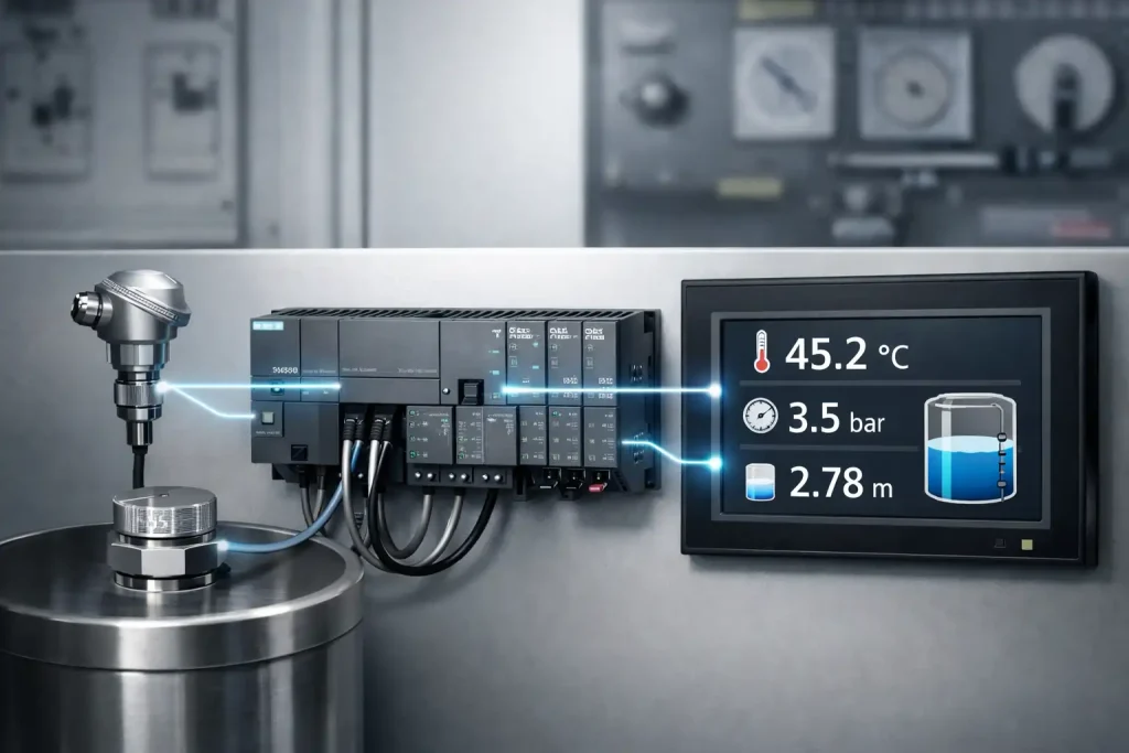
One of the most important beginner concepts is Analog Scaling in PLC. Without it, a temperature, pressure, or level sensor connected to a PLC becomes meaningless numbers on the HMI screen.
In this guide, we’ll understand analog scaling practically – the same way an automation engineer uses it in real projects.
What is Analog Scaling in PLC?
When a sensor sends a signal to a PLC, the PLC does NOT understand it as temperature, pressure, or level.
Instead, the PLC receives a raw digital value.
Example:
- Sensor sends: 0-10V or 4-20mA
- PLC reads: 0 to 27648 (raw counts)
So if your HMI shows 13824, the operator cannot understand anything.
Analog scaling simply converts that raw number into a real-world engineering value the operator can understand.
- 45°C temperature
- 3 bar pressure
- 2.5 meter tank level
This conversion process is called Analog Scaling.
Why Analog Scaling is Important in Industrial Automation
Many beginners think scaling is only for display.
In real plants, it controls the entire process behavior.
Without scaling:
- HMI displays useless numbers
- Operator cannot control process
- Alarms won’t work properly
- PID control will fail
- Plant automation becomes unreliable
With scaling:
- Real-world value appears on screen
- Alarm limits work correctly
- PID tuning becomes possible
- Process control becomes stable
So even though this is a basic PLC programming concept –
it is critical for real industrial automation projects.
Raw Analog Value in S7-200 Smart PLC
In Siemens S7-200 Smart PLC, analog modules convert signal into a fixed digital range.
| Input Signal | PLC Raw Value |
| 0-10V | 0 – 27648 |
| 4-20mA | 0 – 27648 |
This value is stored in the Analog Input Word (AIW).
Important thing to remember:
The AIW value is not temperature, not pressure, not level.
It is only a measurement of voltage level converted into numbers.
Engineering Range vs Raw Range
Now we define what that number actually represents in the real world.
This is called the engineering range.
Examples:
| Sensor Type | Engineering Range |
| Temperature | 0 – 100 °C |
| Pressure | 0 – 10 bar |
| Level | 0 – 5 meter |
PLC converts raw value → engineering value using scaling.That mapping process is scaling.
Analog Scaling Formula (Simple Explanation)
The formula may look complex, but concept is simple:
Convert raw range into engineering range proportionally.
Formula
ScaledValue=(ScaledMax-ScaledMin)(RawMax-RawMin)×(RawInput-RawMin)+ScaledMinSca
led Value = \frac{(Scaled Max – Scaled Min)}{(Raw Max – Raw Min)} \times (Raw Input – Raw Min) + Scaled
MinScaledValue=(RawMax-RawMin)(ScaledMax-ScaledMin)×(RawInput-RawMin)+ScaledMin
This gives the actual process value.
PLC reads position in electrical scale
We convert it into physical scale
Example Calculation
Let’s say: Suppose a temperature sensor works from 0 to 100°C.
- Sensor range = 0 to 100°C
- PLC raw range = 0 to 27648
- Raw input = 12000
After scaling:
Output ≈ 43.4°C
Now the operator understands the real temperature.
Ladder Logic Flow for Scaling
In real PLC programming, engineers don’t apply the formula directly in one instruction. They break it into logical steps so troubleshooting becomes easy.
We perform step-by-step calculation:
- Move analog input to memory word
- Subtract raw minimum
- Multiply by engineering range
- Divide by raw range
- Add engineering minimum
- Store final value in float register
This final value is used in:
- HMI display
- Alarms
- PID control
- Data logging
Important Programming Tips (Very Important)
1. Avoid Integer Division
Always convert numbers into REAL format before division.Otherwise PLC cuts decimal values and scaling becomes inaccurate.
2. Use Float Registers
Store final scaled value in:
- VD
- FD registers
3. Clamp Minimum & Maximum Limits
Sensors sometimes produce noise. Limit values to avoid abnormal readings.
4. Raw Range is Fixed
For S7-200 Smart:
- Raw Min = 0
- Raw Max = 27648
No need to create tags for it.
Where Analog Scaling is Used in Industry
Analog scaling is used in almost every automation plant:
- Water treatment plant
- Boiler temperature control
- Tank level monitoring
- Flow measurement
- Pressure control system
- Chemical dosing systems
- HVAC automation
Without scaling → automation cannot exist.
Common Beginner Mistakes
Most new PLC programmers make these errors:
- Directly showing AIW value on HMI
- Using integer math
- Wrong sensor range
- Not clamping limits
- Using wrong data type
Because of this, plants show unstable readings.
Final Thoughts
Analog scaling is a small topic but a foundational concept in PLC programming and industrial automation.
If you understand scaling clearly:
You can confidently handle sensors, alarms, and PID logic in any automation project.
Every real factory system depends on correctly scaled values – not raw numbers.
So mastering analog scaling is one of the first steps toward becoming a real automation engineer.
FAQ
1. What is analog scaling in PLC?
Analog scaling converts PLC raw input values (0–27648) into real engineering units like °C, bar, or meter so operators can understand and control the process.
2. What is the raw input range of S7-200 Smart PLC?
Siemens S7-200 Smart converts 0–10V or 4–20mA signals into a digital value between 0 and 27648.
3. Why does HMI show the wrong sensor value?
Because scaling is missing, wrong range is set, or integer math is used instead of real (float) calculation.
4. Where is analog scaling used?
It is used in temperature, pressure, level, flow measurement, PID control, and all industrial automation systems.
5. Why is real (float) data type used in analog scaling?
Because scaling involves division and decimals; using integer data type gives inaccurate values, while float (REAL) provides correct process readings.